Overview and Core Functions of Motorized Smoke Barriers
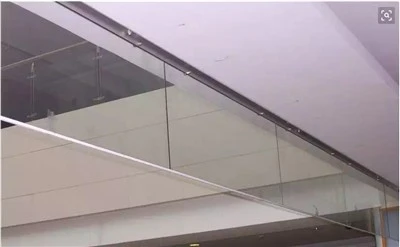
►Motorized smoke barriers are essential components of the smoke control and exhaust systems in modern large-space buildings. Their core function is to provide intelligent movable partitioning. Normally retracted and concealed within ceilings, they do not occupy usable indoor space, balancing architectural aesthetics, daily building functions, and the fire safety requirement of smoke containment. In engineering practice, the full lifecycle quality must be strictly controlled in accordance with current fire protection codes, including product selection, detailed design, installation, linkage acceptance, and long-term maintenance.
►In the event of a fire, motorized smoke barriers descend automatically upon receiving fire linkage signals to form vertical smoke-retaining barriers and divide the building into designated smoke compartments. They restrict the horizontal spread of hot smoke along the ceiling and form effective smoke reservoirs. Reliable operation, qualified smoke barrier performance and compliant linkage logic are essential to ensure proper smoke compartment function, mitigate hazards from smoke spread, strengthen building fire safety, extend safe evacuation time for occupants, reduce risks of smoke asphyxiation and toxic inhalation, and create favourable conditions for fire rescue operations.
Basic Structure and Working Principle

1. Overall Structure
Curtain body: The core smoke-retaining component, which must meet Grade A non-combustibility requirements, fire resistance integrity criteria and smoke leakage indicators (smoke leakage ≤ 25 m³/(m²·h)). The lap width of multi-panel flexible curtains shall be no less than 100 mm to reduce smoke bypass risks.
Drive system: Special tubular fire-resistant motor, reducer and reel transmission mechanism for curtain retraction and descent; equipped with a 220 V AC main power supply and standby power supply, to ensure complete emergency descent for no less than 3 times when the main power fails.
Control system: Dedicated smoke barrier controller, fire linkage modules, limit sensors, local manual control box (mounted 1.3~1.5 m above finished floor), fusible alloy thermal release device (typically rated at approximately 73℃); capable of uploading upper/lower limit status feedback signals to the fire alarm control panel for real-time status monitoring.
Structural frame: Ceiling storage enclosure, vertical guide rails, weighted bottom beam and fixing brackets. Fire-resistant sealing strips are fitted inside guide rails, and gaps between enclosures and floor slabs are sealed with fireproof materials to prevent smoke from spreading through ceiling voids.
2. Working Principle
Normal mode: The curtain is fully retracted inside the ceiling enclosure, flush with the ceiling, without interfering with daily passage or interior finishes.
Automatic linkage mode: When two independent smoke detectors within the same smoke compartment trigger an alarm via AND logic, the fire linkage controller sends an activation command. The barrier shall act in compliance with specified timing requirements: the command shall be issued by the fire alarm control panel within 15 seconds after fire confirmation, and full descent shall be completed within 60 seconds, forming and locking a vertical smoke barrier with a minimum effective depth of 500 mm, while transmitting the in-position signal back to the fire control room panel.
Manual control mode: Descent can be controlled remotely via the fire control room panel or local on-site buttons. Electric retraction and reset can only be performed through formal reset procedures after the fire alarm is cleared.
Emergency backup mode: Automatic descent via standby power supply or gravity upon main power failure; when ambient temperature reaches the threshold of the thermal release device, the fusible alloy melts and releases the curtain to enable gravity descent. This ensures smoke barrier function under extreme conditions of power loss and signal failure. After descent, the clear passage height shall comply with building evacuation requirements (typically ≥ 2.0 m) to avoid obstructing evacuation routes.