Products Description
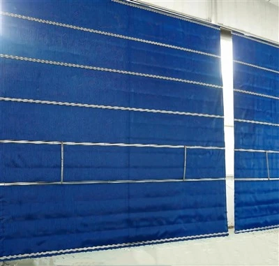
Motorized smoke barriers are critical fire evacuation facilities, and their stable operation directly determines the effect of fire smoke control. Operation and maintenance personnel shall strictly implement the daily operation, classified maintenance and troubleshooting procedures specified in this specification, conduct regular inspections and standardized tests, and rapidly close the loop of fault disposal. Eliminate hidden risks of equipment failure, ensure the integrity and effectiveness of the building smoke prevention and exhaust system, and comply with fire protection codes as well as emergency evacuation safety requirements.
Specification for Common Fault Phenomena and Disposal
Fault Phenomenon 1: The barrier fails to lower completely after linkage alarm trigger
Circuit fault: Broken signal wire & loose terminals → Check wiring, re-crimp terminals and reset address coding.
Limit switch stuck: Upper limit fails to release → Reset limit paddle and calibrate stroke.
Module failure: No linkage output → Replace I/O module and re-match fire alarm host.
Fault Phenomenon 2: No backup power available after power failure, emergency lowering fails
Causes: Aging undercharged storage battery, damaged charging circuit.
Disposal: Replace dedicated backup battery immediately; overhaul charging board and test battery capacity by power cut monthly.

Fault Phenomenon 3: Barrier stops halfway and cannot lock fully in place
Causes: Misaligned lower limit switch, stuck reel, insufficient counterweight on bottom beam.
Disposal: Clean transmission mechanism, calibrate lower limit position; add counterweight blocks and retest full lowering time sequence.
Fault Phenomenon 4: No feedback signal received by fire control main unit
Causes: Broken feedback wire, damaged feedback module of controller.
Disposal: Inspect feedback circuit, replace faulty module, repeatedly test lifting and lowering to confirm real-time status reception by main unit.
Four Standard Operating Procedures

(1) Automatic Linked Operation (Standard Fire Condition)
When two independent smoke detectors in the same smoke compartment send out alarms sequentially to meet the "AND logic" condition, the controller will automatically send a lowering command. The curtain will descend at a constant speed until it reaches the limit position and locks in place. The main unit in the fire control room will receive the feedback signal indicating full lowering, and the smoke exhaust fan will start synchronously via linkage. A false alarm from a single smoke detector will not trigger any movement to avoid accidental lowering that obstructs passage.
(2) Local Manual Operation (On-site Emergency)
Press the "DOWN" button on the local push-button box to lower the barrier; press "STOP" midway to hold it in position. After full lowering and locking, a special key is required to unlock the device before manual reset and lifting. When power is cut off, pull the emergency zipper at the bottom to force the barrier down.
(3) Remote Operation via Fire Control Room
Duty officers select the corresponding compartment point on the fire alarm linkage panel to send a remote lowering command. The control room can only execute lowering and cannot remotely reset or lift the barrier; resetting must be completed on site.
(4) Mechanical Emergency Operation Under Power Failure (When both main power and backup power fail)
Use a special key to open the cabinet release mechanism; turn the manual release shaft or pull the emergency zipper to release the reel lock. The curtain will descend evenly to the smoke-blocking height relying on the dead weight of the weighted bottom beam.
Standard for Routine Maintenance and Inspection

1 Daily Visual Inspection (Property Duty Staff)
Appearance: No tearing, holes, aging or degumming on the curtain; no deformation or rust on the cabinet and guide rails; all fixing bolts are tight; fireproof sealing brushes and bottom beam rubber strips remain intact. Environment: No stacked obstructions in the lowering path; no cracked or exposed wires; local push-button box intact without damage. Status: No fault alarm indicator light on the controller; the equipment stays powered on in standby mode.
2 Monthly Full-Function Test (Certified Maintenance Personnel)
Test all four operation modes respectively: automatic linkage, local manual control, remote control and mechanical emergency operation. Measure actual lowering duration and height, and verify feedback signals transmitted to the fire control main unit. Conduct power-off test for lowering function powered by backup battery; replace storage batteries immediately if voltage is insufficient. Clear dust and debris inside guide rails, and check the sensitivity of limit switches.
3 Quarterly Special Maintenance
Clean cabinets, motors and guide rails, and apply high-temperature resistant grease to transmission bearings. Tighten all wiring terminals and test that circuit insulation resistance is no less than 20 MΩ. Inspect 73 ℃ fusible links for deformation and corrosion, and replace aged sealing strips. Adjust curtain tension to eliminate smoke leakage gaps on one side of the guide rails.
4 Annual In-Depth Overhaul (Performed by Institutions with Fire Inspection Qualification)
Disassemble motors to test insulation resistance and operating current; replace worn carbon brushes and aged reels. Fully calibrate linkage logic and issue an official fire protection facility inspection report. Repair damaged curtains, rectify deformed guide rails, and re-seal fire gaps on the top of cabinets. Replace backup storage batteries that have been in service for 1 to 2 years, and update equipment files.